CNC machining and CMM inspection software form the practical backbone for small-to-medium (SMB) contract shops that need to increase throughput, reduce rework, and make staffing decisions based on measured operator workload. This guide explains CNC fundamentals, high-impact program optimizations, how to turn machine monitoring into measurable capacity gains, and how CMM inspection software closes the quality loop so fewer parts are reworked or scrapped. Read on for concrete tactics—percent savings, integration pathways, and vendor/technology trade-offs—that operations and production leaders can act on immediately.
TL;DR:
-
Target 10–40% cycle-time reductions with focused CAM/G-code changes (adaptive milling and feed optimization commonly deliver 10–40% on roughing and 5–15% on finishing).
-
Use automated monitoring to capture spindle/program/events and reduce admin/manual logging, improving utilization by 10–25% and shortening reaction time to failures.
-
Integrate CMM inspection software for automated routines and SPC so rework/scrap on critical parts can drop 30–70%; run a small pilot linking cycle-time capture and inspection before scaling.
What Is CNC Machining and Why Does It Matter for Small-to-Medium Shops?
CNC fundamentals: machines, tools and materials
CNC (computer numerical control) machining uses pre-programmed commands (G-code) and CAM-generated toolpaths to drive mills, lathes, mill-turn centers, multi-axis machines, and Swiss machines. Common machine types in SMB shops include vertical/horizontal mills, 2–.5 to 5-axis mills, CNC lathes, and mill-turn centers. Typical tooling systems include solid carbide end mills, indexable-insert turning tools, and modular tooling for high-repeatability setups. Materials most often machined are aluminum, mild and stainless steel, titanium alloys, and engineering plastics. Spindle speeds and feeds depend on tool material and work material—shops commonly tune rpm and feed per tooth based on manufacturer recommendations or NIST-like datasets.
Common shop metrics: throughput, OEE, cycle time
Operations leaders track throughput (parts/hour), OEE (availability × performance × quality), and cycle time (actual time to produce one part). OEE frameworks help quantify where losses happen; for many SMB shops a 10–20% OEE improvement is realistic within months of implementing monitoring and program optimizations. Research and industry case studies show incremental CAM/G-code changes and monitoring commonly yield 10–30% cycle-time reductions depending on part geometry and process maturity.
When CNC is the right tool for your production mix
CNC outperforms manual machining when repeatability, precision, and higher batch sizes matter. For prototype or one-off work, setup time can dominate; for low-to-medium volume contract runs, optimized CNC programs and fixturing reduce per-part cost and lead time. Prioritize program optimization before hiring when existing staff are constrained but machines run below capacity—improvements to G-code, tooling, and cycle-time capture often unlock capacity equal to hiring additional operators without added payroll. For shops pursuing defense contracts or handling controlled data, planning for cybersecurity and compliance is essential; see the Department of Defense guidance on Level 2 self-assessment and certification here: CMMC Assessment Guide – Level 2 | Version 2.13.
How Can CNC Program Optimization Reduce Cycle Time and Increase Capacity?
High-impact CAM and G-code strategies
Program-level changes often deliver the highest impact per engineering hour. Adaptive or trochoidal milling paths keep the tool cutting at a consistent chip load, enabling much higher material removal rates with lower thermal and mechanical shock. Industry reports and vendor benchmarks indicate adaptive strategies can reduce roughing time by 10–40% versus conventional zig-zag roughing depending on material and machine rigidity. Other high-impact tactics include minimizing non-cutting moves (rapid retracts and dwell removal), combining operations to reduce tool changes, and using pocketing strategies that maintain constant engagement.
Toolpath choices and cutting parameter tuning
Choose toolpaths that match machine capabilities: high-feed milling and trochoidal paths for hard materials, high-speed finishing passes with small stepover for tight surface finish. Tune step-over, step-down, and feed-per-tooth using tooling vendor data and machining handbooks; where available, reference NIST or tooling vendor tables for starting parameters. Adjust spindle speed and feed rates incrementally and measure part quality, tool wear, and cycle time. Fixture rigidity and workholding directly affect achievable feeds/speeds: clamps and modular vises that reduce chatter allow higher metal removal rates.
Using cycle-time estimates from CAM versus measured times
CAM-generated cycle-time estimates are useful for planning but often diverge 5–30% from measured machine times because they assume ideal axis accelerations and no operator interventions. Extracting cycle or standard times from the NC program and validating with machine monitoring produces accurate planning data and avoids schedule drift. For a real-world example of program optimization delivering measurable savings, see this CNC programming case study. Track before-and-after with a monitoring system to quantify gains and iterate.
What Practical Steps Turn Machine Monitoring and Tracking into Higher Throughput?
Which machine signals and events to capture
Effective monitoring captures a minimal essential set of signals: cycle start/stop timestamps, spindle run status, program number, alarm codes, part counts, and basic axis activity. Additional useful inputs include tool change events, coolant status, and probe-inspection confirmations. Capture of these signals allows computation of actual cycle times, downtime reasons, and first-pass yield. Typical capture methods are PLC I/O taps, MTConnect or OPC UA when supported by the controller, and edge devices that read machine signals or parse NC program headers.
Operator workload and manual intervention tracking
Operator interventions (loading, unloading, setup, offsets) are a major source of variance. Monitoring should record manual action events—either via simple operator push-buttons attached to machines or by combining program state with camera/IoT inputs—to quantify average touch time per part and total operator load. That data supports lean staffing decisions: when monitoring shows machines consistently running with low operator interaction, shops can reallocate labor to setup or secondary operations rather than hiring. Studies and vendor benchmarks indicate automated tracking reduces administrative logging time by up to 80% and improves utilization 10–25% compared with manual logbooks.
From data to action: dashboards and alerts
Transform raw signals into operational metrics and actionable alerts: real-time dashboards should show OEE components, actual vs. standard cycle time, and first-pass yield by job. Set thresholds for exception alerts (tool break, spindle overload, program mismatch) to shorten response times. Automated dashboards that integrate with scheduling systems enable dynamic rescheduling when a machine falls behind. For deeper reads on available software approaches and benefits for CNC monitoring, see this overview of machine monitoring software and practical advice on automated production tracking. Academic research into hybrid machine-control and monitoring systems provides further validation that in-process monitoring can be used to improve throughput and reduce rework: see related work on flexible machine tool control systems hosted by Brigham Young University (BYU) here: scholarsarchive.byu.edu
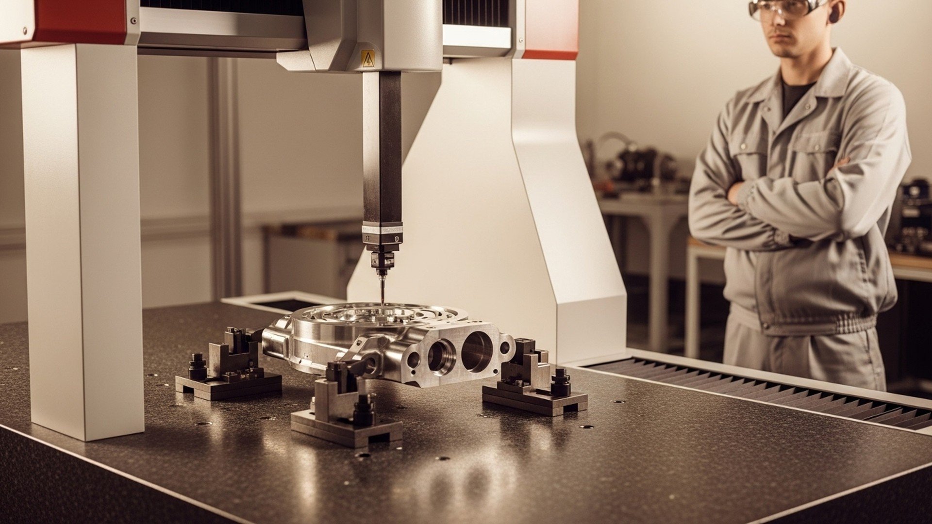
How Do CMM Inspection and CMM Inspection Software Fit into a Shop’s Quality Workflow?
Roles of CMM hardware vs inspection software
Coordinate measuring machines (CMMs)—bridge-style, gantry-style, and portable arms—provide dimensional verification across complex geometries and tight tolerances. Hardware accuracy can reach micron-level performance in temperature-controlled environments; portable arms trade some absolute accuracy for flexibility on the shop floor. Inspection software (PC-DMIS, Calypso, Mitutoyo software suites, and cloud platforms) schedules routines, translates CAD/GD&T into probe paths, and executes measurement sequences. The software is the bridge between CAD nominals and physical measurement, enabling repeatable programs and traceable data.
How software automates measurement routines and reports
Inspection packages automate probe path generation, data capture, and reporting. Common features include CAD import, GD&T interpretation per ASME Y14.5, multi-probe support, and SPC charting. Automated routines reduce operator variation and shorten inspection turnaround. Industry experience suggests that integrating CMM inspection software with production workflows reduces scrap and rework on critical features by 30–70% because deviations are caught earlier and disposition decisions are faster. Government inspection manuals also describe CMM roles in dimensional verification and traceability; see the operations manual for inspection workstations for authoritative procedures: govinfo.gov
Closing the loop: feeding inspection results back to production
A key benefit of modern inspection software is the ability to close the loop: inspection outputs (coordinate deviations, feature trends) feed back into CAM/CNC offsets, tooling changes, or process corrective actions. For example, a persistent datum error detected by CMM can be translated into fixture offset adjustments in the CNC, preventing a run of nonconforming parts. Shops that automate disposition and integrate inspection data with MES see faster corrective actions and fewer repeated mistakes. To understand practical connections between CMMs and shop-floor systems, review Jitbase’s guidance on connecting CMMs. For a hands-on demonstration of how inspection routines are programmed and executed, watch this tutorial: .
How to Choose CMM Inspection Software: Comparison and Specs Table
Required features checklist
When selecting inspection software, prioritize:
-
CAD import and model alignment
-
Full GD&T support (ASME Y14.5 compatibility)
-
Multi-probe and multi-sensor support (touch probe, laser scanner)
-
Automation and API connectivity (REST/OPC UA)
-
SPC and reporting with export options (CSV/Excel/REST)
-
Licensing model and local support/training options
Comparison/Specs table: capabilities vs shop needs
| Category | CAD import | GD&T support | Multi-probe | Automation/APIs | SPC/Reporting | Integration | Typical shop fit |
|---|---|---|---|---|---|---|---|
| Basic offline teach | Yes | Basic | Limited | Minimal | Basic CSV | CSV export | Prototype, low-volume |
| Full metrology suite (PC‑DMIS / Calypso) | Yes | Full ASME Y14.5 | Yes | APIs / scripting | Advanced SPC | OPC/CSV/REST | High-volume, regulated |
| Portable arm software | Yes | Partial | Arm probes only | Limited APIs | Basic charts | CSV/REST | Flexible/field inspection |
| Cloud-enabled inspection platforms | Yes | Full/Configurable | Varies | REST APIs, webhooks | Real-time SPC & dashboards | ERP/MES integrations | Contract shops, multi-site |
Licensing, support and integration considerations
Expect pricing tiers: entry-level offline packages under $5–10k (one-time or subscription), full suites (PC‑DMIS/Calypso) often in the mid-five-figures per seat with maintenance contracts. Cloud platforms typically use subscription models with per-seat or per-facility pricing. Evaluate vendor responsiveness, available on-site training, and local calibration/metrology support. Confirm API capabilities (REST, OPC UA, CSV export) for integration with MES/ERP systems and ensure the software produces traceable reports for audits. Standards compliance matters—look for explicit ASME Y14.5 alignment for GD&T and ensure inspection data records meet traceability requirements.
For authoritative background on GD&T standards and expectations, review ASME’s page on dimensioning and tolerancing: asme.org
What Does Integrating Machine Monitoring and CMM Data with ERP/MES Look Like?
Data flows: NC program → machine → monitoring → inspection → ERP
A typical integration pipeline starts with NC program metadata (part number, operation, estimated cycle time) associated with a work order. The machine executes and the monitoring system captures actual cycle times and events. After production, CMM inspection software records measurement results and yields. These datasets—actual cycle time, part dispositions, and SPC trends—are pushed to ERP/MES to update job progress, inventory, and quality records. Automating this flow removes manual entry, shortens order-to-ship, and gives planners accurate lead-time inputs.
Common integration methods and APIs
Reliable integration uses industrial protocols and web APIs: MTConnect and OPC UA for machine telemetry, MQTT or REST APIs for event streaming, and CSV/REST endpoints for inspection exports. Many ERP systems (Epicor, abas, SAP Business One) expose REST or SOAP APIs for programmatic updates; MES platforms accept job-status updates and can trigger downstream workflows. Architect integration with clear identifiers (work order numbers, program names, and serialized part IDs) to avoid part misattribution.
Use cases: automated part disposition and updated cycle times
Use cases unlocked by integration include automated pass/fail part disposition (inspection result triggers quarantine or release), automatic nonconformance reports to QA with attached measurement logs, and dynamic updating of cycle-time standards when measured times deviate from CAM estimates. Feeding measured cycle times back into planning databases improves schedule accuracy and reduces late deliveries. Practical ROI includes fewer shipping delays, lower scrap, and reduced admin: shops frequently report a 30–60% reduction in time spent on manual paperwork after integrating shop-floor systems with ERP/MES. For more on how real-time machine data enhances scheduling, see this explanation of real-time scheduling.
Implementation Checklist and Key Metrics to Measure Success
Project milestones and pilot checklist
Start with a small pilot cell and clear milestones:
-
Baseline measurement: collect current cycle times, OEE, and inspection turnaround.
-
Pilot selection: choose a representative part family or cell with measurable throughput pain points.
-
Hardware/software integration: install sensors/edge devices, configure MTConnect/OPC UA, and set up CMM routines.
-
Operator training: run short hands-on sessions and establish operator event logging practices.
-
Dashboard tuning and alerts: configure KPI thresholds, dashboards, and reporting.
-
Review & scale: evaluate pilot against KPIs and roll out in phases.
Key metrics to track during rollout
Monitor:
-
OEE change (availability, performance, quality)
-
Cycle time variance (actual vs. standard)
-
First-pass yield and rework/scrap rates
-
Inspection turnaround time and number of nonconformances
-
Manual action counts per shift and data coverage percentage (percent of machines and ops monitored) Short-term wins typically include reduced admin time and immediate visibility into bottlenecks; medium-term gains often show utilization increases of 10–25% and measurable reductions in rework.
Common pitfalls and how to avoid them
Avoid inconsistent part identification, missing machine signals, and poor change management. Ensure naming conventions for programs and work orders are standardized, verify signal availability before hardware installation, and involve stakeholders early (manufacturing engineer, shop manager, QA lead, controls vendor, IT). Pilot slowly, validate data quality before trusting dashboards, and schedule buffer time for training and process adjustments.
The Bottom Line
SMB CNC shops that pair targeted CNC program optimization with systematic machine monitoring and appropriate CMM inspection software can increase throughput, reduce rework by 30–70% for critical parts, and make staffing decisions based on measured operator workload. Recommendation: run a focused pilot that captures cycle-time and inspection data, validate results, then scale integration with your MES/ERP.
Frequently Asked Questions
How accurate are CMM machines and software for typical shop parts?
CMM accuracy depends on hardware class and environment: bridge-style lab CMMs routinely achieve micron-level accuracy (single-digit micrometers) in temperature-controlled rooms, while portable arms are typically accurate to a few tens of micrometers. Software accuracy relates to probe calibration, measurement strategy, and correct CAD/nominal alignment; following probe qualification routines and using traceable calibration reduces systematic error. For shop-floor applications, specify the required tolerance band and select CMM hardware/software that maintains required uncertainty with a traceable calibration schedule.
Can CMM inspection software run automated routines without an operator?
Yes—when parts are fixtured repeatably and probe paths are validated, inspection software such as PC‑DMIS and Calypso can execute fully automated routines including multi-probe exchanges and automatic reporting. Automation requires consistent part loading, reliable probe calibration, and integration with job identifiers so results are correctly attributed. Many shops use automated cells for batch inspection and route outliers to manual inspection or quarantine workflows.
What machine signals are essential for measuring cycle time?
The minimum signals are cycle start/stop timestamps, spindle run or spindle speed, and program number. Alarms, part counts, and tool-change events are also valuable for diagnosing variance. Capture via MTConnect, OPC UA, or simple PLC I/O taps; validate that timestamps are synchronized and that program names match work orders to ensure accurate per-job cycle-time attribution.
How long does it take to see ROI from monitoring and inspection integration?
ROI depends on scope: small pilots often show admin savings and visibility benefits within 1–3 months, while full integration (monitoring + inspection + ERP/MES) typically pays back within 3–12 months through reduced rework, higher utilization, and faster shipping. Quantify expected savings up front—time saved on manual logs, reduced scrap, and recovered machine hours—and measure those against implementation costs for a realistic timeline.
Do I need to replace my existing CAM/CNC to get benefits?
No. Most gains come from improving existing CAM strategies and extracting measured cycle times from current NC programs rather than replacing controllers. Adaptive toolpaths and feed tuning are CAM-level changes, and monitoring/CMM integrations typically work with existing equipment using MTConnect, OPC UA, or edge devices. Replace only when machine capability or controller limitations prevent necessary process improvements.
Related Articles


